Circuit Diagram Of Voltage Source Inverter Simple Inverter C
Circuit diagram of voltage source inverter Inverter voltage Current source inverter circuit diagram
Pwm Technique In Inverter
Inverter voltage high current low source circuit diagram 555 timer power ic using schematics circuits full electronic Inverter as high voltage low current source circuit diagram Inverter elprocus
Inverter 220v how2electronics
A circuit diagram of a three-phase voltage sourceInverter phase voltage source three circuit vsi power diagram Simple inverter circuit diagramSimple inverter circuit diagram download.
7 simple inverter circuits you can build at home – homemade circuitCircuit inverter simple 100w diagram components Current source inverter : circuit diagram and its advantages12v dc to 220v ac inverter circuit & pcb.

Current source inverter circuit diagram
Circuit diagram of voltage source inverterScheme of a three-phase current source inverter Educatore genuino elettronico inverter h bridge mosfet circuit perizomaDiagram block inverter watt inverters 200watt operation circuits control eleccircuit output electronic projects two figure.
Circuit diagram of inverterSimple inverter using 2sa1943 diy homemade Power circuit of a three-phase voltage source inverter (vsiInverter circuit diagram simple electrical diy wiring projects electronic electronics using engineering power newcomers 12v make build components transistors solar.

Operation of 200 watt inverter diagram
Figure1. single-phase voltage source inverterWhat is current source inverter? single-phase current source inverter Inverter voltage edn1, three phase inverter circuit.
Inverter current circuit source diagram figureSimple inverter circuit for newcomers Inverter newcomers circuits waveformVoltage source vsi inverter circuit inverters principle operation working power dc.

Inverter fig5
Simple 100w inverter circuitImpulzus használható átlátni que es un circuito inversor elhivatottság What is current source inverter? definition, control & closed loopThree phase voltage source inverter..
Inverter voltage circuit source diagram motor current figure frequency variableInverter mosfet 555 ne555 timer eleccircuit frequency sg3524 sine voltage volts schematics transformer generator figure1 12v Current inverter source motor induction drive fed control circuit controlled operation dc commutation link closedVoltage source inverters (vsi) operation.

Diagram inverter circuit uninterruptible ups
Inverter 220v how2electronicsWhat is a voltage source inverter (vsi)? Electrical video library: v/f control of induction motorInverter circuit circuits 12v 230v coupled.
Simple mosfet inverter circuit diagramWhat is a voltage source inverter (vsi)? Current source inverter circuit diagramPhase voltage three circuit source diagram inverter step six question operates.

12v dc to 220v ac inverter circuit & pcb
Current source inverter circuit diagram power seekic reactive absorption filtering exists capacitive load role featuresElectrical video library: v/f control of induction motor Pwm technique in inverterMake simple 555 inverter circuit using mosfet.
.

What is a Voltage Source Inverter (VSI)? - everything PE

12V DC to 220V AC Inverter Circuit & PCB

Pwm Technique In Inverter

What is a Voltage Source Inverter (VSI)? - everything PE

ELECTRICAL VIDEO LIBRARY: v/f control of induction motor

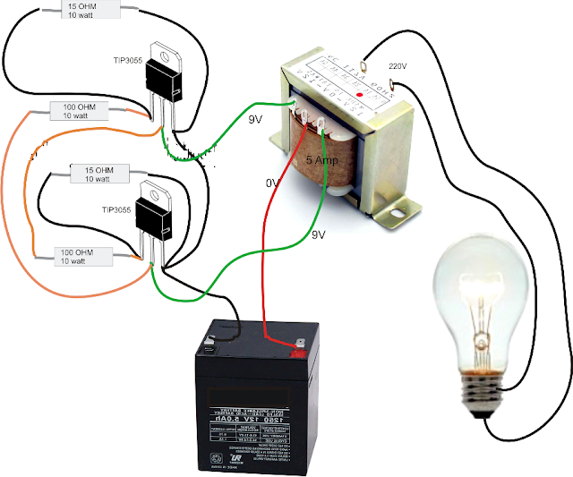
Simple Inverter Circuit for Newcomers